Blog
3D Mouse Workflow for Mechanical Part Inspection
Jul
A 3D mouse workflow for mechanical part inspection should be slow, repeatable, and tied to specific geometry. The point is not to rotate the part constantly. The point is to inspect holes, edges, clearances, wall thickness, hidden faces, fastener access, and manufacturing-sensitive features without losing orientation.
Mechanical inspection works best when you follow a path. Start with the overall shape, move to functional faces, check interfaces, inspect risky details, and finish with export or drawing-review questions. A 3D mouse helps because it can keep movement continuous while the regular mouse selects, measures, or highlights features. That continuity is useful when small geometry problems only appear from one or two angles.
Begin with the part’s purpose
Before moving the view, state what the part must do. Is it a bracket, enclosure, adapter, hinge plate, fixture, cover, handle, or printed prototype? Purpose tells you what to inspect first. A bracket needs mounting holes and load paths checked. An enclosure needs wall thickness, bosses, vents, and assembly clearance. A fixture needs datum faces and access for tools.
Without purpose, navigation becomes wandering. With purpose, each orbit has a reason. You rotate because you need to see whether a screw head clears a wall, whether a fillet interrupts a mating face, or whether a hidden surface is manufacturable.
Inspect outside shape before small details
Use the 3D mouse to make a slow loop around the part. Check the silhouette, major faces, protrusions, and overall proportions. Do not zoom into every hole immediately. The outside pass helps you understand orientation and spot obvious modeling errors before detailed inspection begins.
After the outside pass, move closer to the feature groups. For holes, inspect both entry and exit sides. For edges, check whether sharp corners need fillets or chamfers. For slots, look at tool access or print orientation. For bosses, check wall connection and nearby clearance. This kind of step-by-step viewing is where dedicated navigation becomes useful.
Use selection and measurement with the regular mouse
The 3D mouse should position the model; the regular mouse should do the inspection actions. Select faces, check dimensions, measure distances, and review feature properties with the normal mouse while the navigation hand keeps the view readable. This is the same division described in the two-handed CAD workflow guide.
If you keep switching the normal mouse between selection and view movement, inspection becomes choppy. A 3D mouse can reduce that interruption, especially when you need to look around a feature from several sides before deciding whether it is acceptable.
Check interfaces and hidden faces
Mechanical problems often appear where parts meet. Use section views, transparency, or temporary hides to inspect mating faces, screw access, bearing seats, connector openings, and internal clearances. A 3D mouse is helpful here because it lets you slowly move around the interface while keeping the measurement or section tool active.
Hidden faces deserve special attention. A face that looks fine from the front may create tool-access issues, print support problems, or assembly interference from another angle. If the part will be 3D printed, pair this workflow with 3D mouse checks for 3D printing designs.
Connect inspection to drawings and review
Part inspection does not end in the 3D view. You may need to create or review engineering drawings, communicate issues to a teammate, or prepare screenshots for a supplier. Use saved views or standard orientations to capture evidence after inspecting the part dynamically.
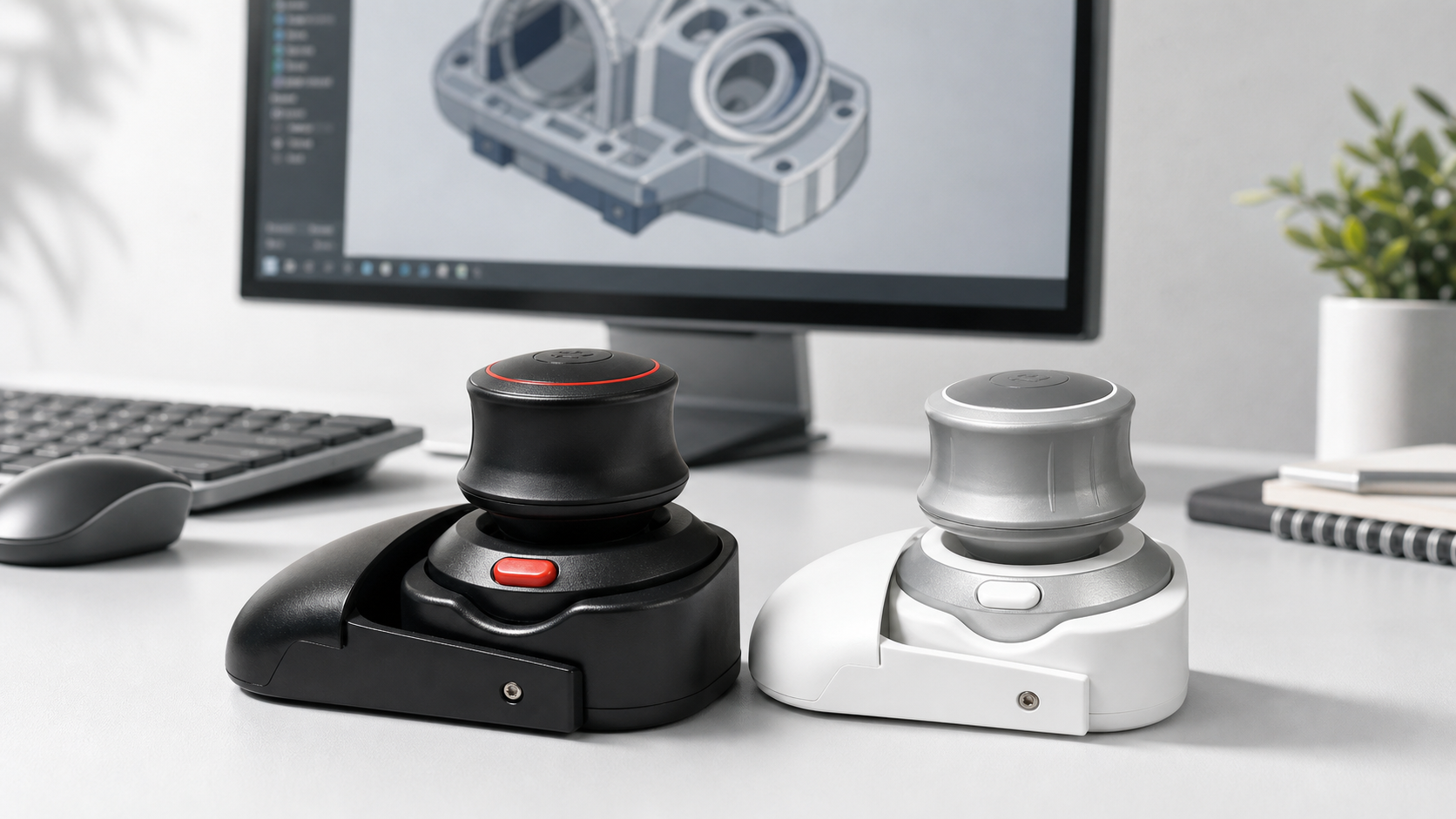
The Wireless 3D CAD Mouse can serve as the navigation side of that review desk: move the model with one hand, select and measure with the other, then capture views for drawings or comments. For drawing-specific review, see using a 3D mouse for engineering drawings and model review.
Inspection checklist
- Identify the part’s purpose before moving.
- Make one slow outside pass around the whole shape.
- Inspect holes, edges, fillets, bosses, slots, and mating faces.
- Use section, hide, and transparency tools for hidden geometry.
- Capture saved views or screenshots for review evidence.
FAQ
Is a 3D mouse useful for small parts?
Yes, if the part has details that need inspection from several angles. Lower sensitivity is important for small geometry.
Should I inspect while continuously rotating?
No. Use small movements, pause at useful angles, inspect a feature, then move again. Constant rotation can hide problems.
What features should I check first?
Start with functional geometry: mounting holes, mating faces, clearances, wall thickness, fastener access, and manufacturing-sensitive edges.
Does this replace measurement tools?
No. The 3D mouse helps position the model. Measurement, section, interference, and drawing tools still provide the actual evidence.
Inspection takeaway
A strong mechanical inspection workflow uses a 3D mouse for controlled viewing, not random movement. Inspect the part by purpose, check details in a repeatable order, and use CAD tools for evidence. The result is a calmer review and fewer missed geometry issues.